

Related Posts
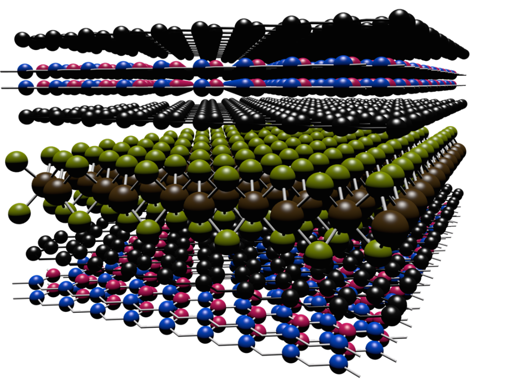
Scientists have developed a way to engineer new forms of matter by stacking different types of layers, each only one atom thick, on top of one another.

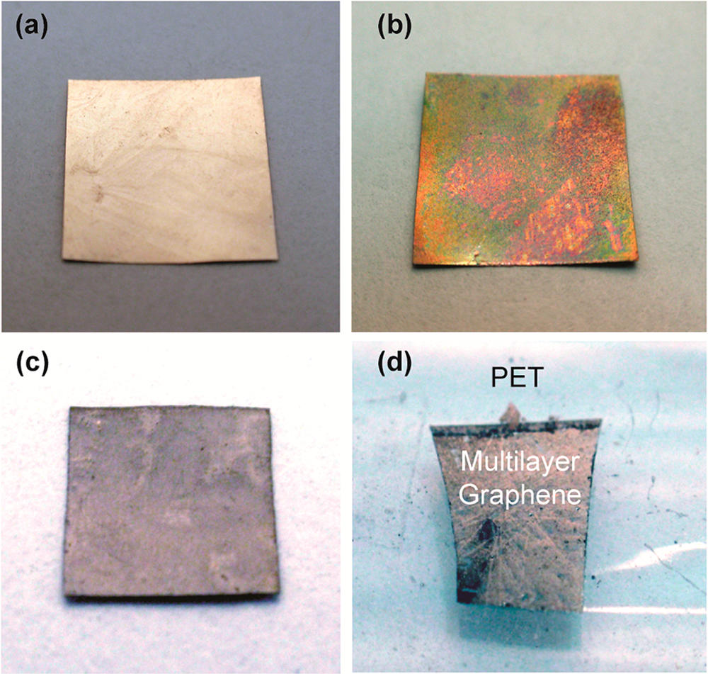
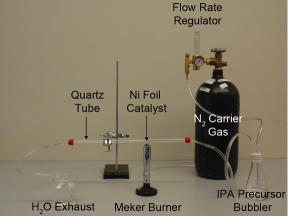
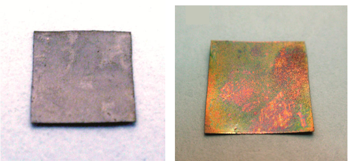
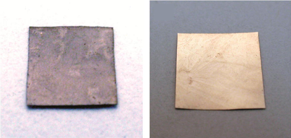
Graphene is a two-dimensional material made from a single sheet of atoms, with outstanding mechanical, electronic, and thermal properties. It is a promising candidate to enable next-generation technologies in a wide range of fields, including electronics, energy, and medicine. This economical, safe, and simple lab activity allows students to make graphene via chemical vapor deposition in 30–45 minutes in a classroom setting.
More Funsize Activities
Students learn how some crystals produce electricity when squeezed! This lesson is part 4 of a 4-part student-driven, lecture-free series, in which students will do card sorts, build hands-on models, solve engineering design puzzles, and more!
Students make paper models of crystal unit cells and build a large crystal structure together while reflecting on the role of symmetry in crystal formation. This lesson is part 3 of a 4-part student-driven, lecture-free series, in which students will do card sorts, build hands-on models, solve engineering design puzzles, and more!
Through hands-on activities using gumdrops and toothpicks, students will learn about unit cells that make up the repeating structures of crystals like table salt. This lesson is part 2 of a 4-part student-driven, lecture-free series, in which students will do card sorts, build hands-on models, solve engineering design puzzles, and more!
Magnets curve themselves into beautiful patterns called domains, which cannot be seen with the naked eye. Now that magnetic paint and nail polish are easily available, we can use magnets to create all kinds of magnetic patterns which we can see, photograph, erase and rewrite! Click to find out how YOU can paint with magnets!
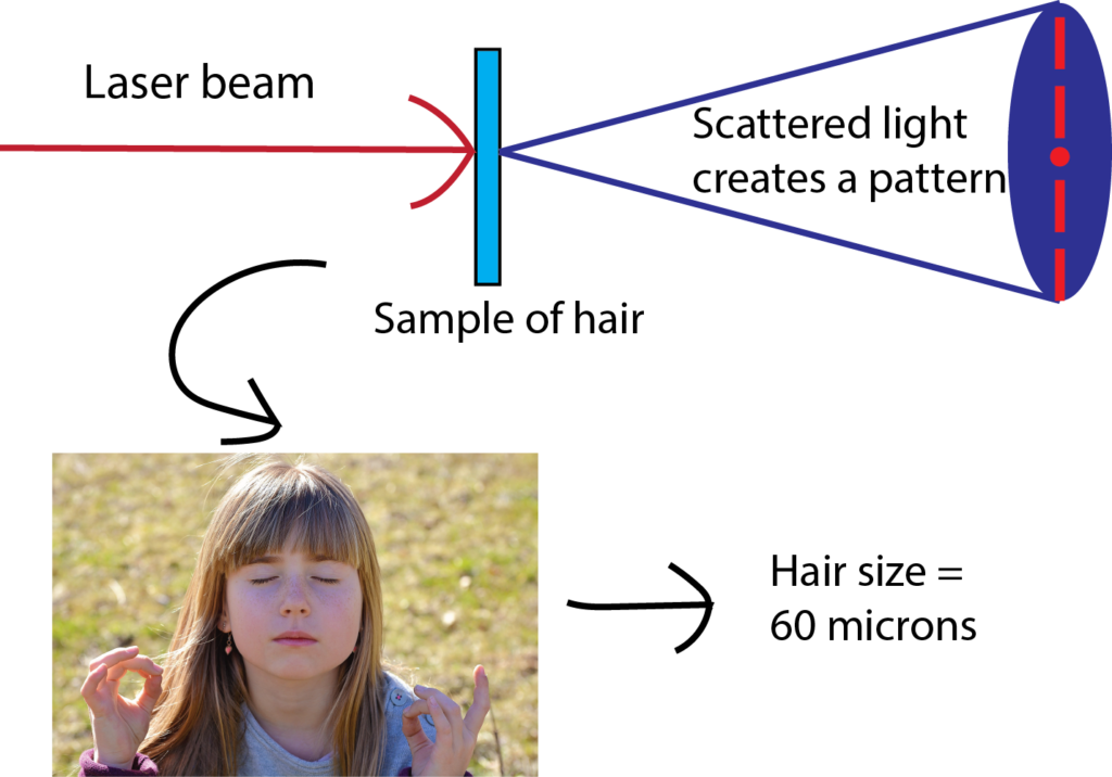
Have you ever wondered how scientists can accurately measure the size of very small objects like molecules, nanoparticles, and parts of cells? Scientists are continually finding new ways to do this, and one powerful tool they use is light scattering. When an incoming beam of light hits an object, the light "scatters," or breaks into separate streams that form different patterns depending on the size of the object. This incoming light might be visible light, like the light we see from the sun, or it might be higher-energy light like X-rays. The light from commercial laser pointers, it turns out, is perfectly suited to measure the size of a human hair!
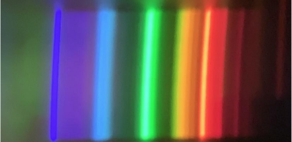
Have you ever wondered why shining light on a glass of water causes rainbows to appear? Or noticed the colors that reflect from a CD or DVD? In this lesson, you will make an instrument called a spectroscope that can separate light into its hidden components. You will also be able to use the spectroscope to understand why different colored objects and light sources appear the way they do.

Self-assembly is the process by which individual building blocks—at the smallest level, atoms—spontaneously form larger structures. The structures they form depend on the size and shape of the building blocks, and on the conditions to which these building blocks are exposed. This can be demonstrated quite simply using breakfast cereal, or for more complex cases using specially prepared Legos.
AtomTouch is a free, interactive molecular simulation app, created by researchers at the University of Wisconsin Materials Research Science and Engineering Center (UW MRSEC) to allow learners to explore principles of thermodynamics and molecular dynamics in an tactile, engaging way.
Graphene is a two-dimensional material made from a single sheet of atoms, with outstanding mechanical, electronic, and thermal properties. It is a promising candidate to enable next-generation technologies in a wide range of fields, including electronics, energy, and medicine. This economical, safe, and simple lab activity allows students to make graphene via chemical vapor deposition in 30–45 minutes in a classroom setting.
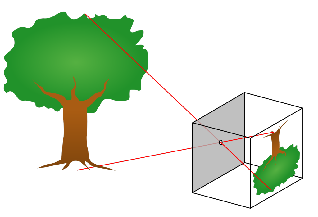
We can easily observe light with our eyes, and so it is one of the most familiar parts of the world around us. And yet, light often does amazing and unexpected things. Light travels in straight lines from the source to our eyes. This fact allows us to understand many of the cool things that light can do. In this lesson, we will observe how light creates mirages and shadows. And we will build a pinhole camera which makes things appear upside-down. We can understand the upside-down images by thinking about the straight line that the light took from the object to the screen.